


Monday, October 21, 2013
Untuk Anda yang ingin Meng-Root Android Anda Khususnya Bagi Pengguna ANDROMAX U2 silakan mencoba :
Peringatan : Resiko di tangung sendiri
Persiapan
Rootmaster Versi 1.7.4
Peringatan : Resiko di tangung sendiri
Persiapan
- Setting HH kamu dalam USB DEBUGGING aktif password : Cobaaja08x
“C” Hufuf Besar. lihat pada gambar.

- Kemudian masuk ke menu security, centang unknown source kemudian

- Hubungkan HH pada PC, lalu lihat pada HH anda akan muncul notifikasi di layar atas, pilih type USB connection pilih “driver setup”

- instal Driver Andromax U2 sampai finish. setelah selesai cabut HH

- Unduh file Rootmaster, lalu instal sampai selesai (install button yang kiri)
- Hubungkan kembali HH ke PC. pastikan pada device manager SuDah tertapilkan ADB interface hisense
 Saat dihubungkan
 Setelah selesai
- Jalankan rootmaster, maka Rootmaster akan mendeteksi HH kamu setelah itu tekan tombol hijau pada rootmaster. ikuti langkahnya sampai selesai.

- HH akan reboot sekali. setelah nyala kembali akan tertampilkan superuser.
 SELAMAT MENCOBA ^_^


Rootmaster Versi 1.7.4
Sudah di coba dan Berhasil
Info : SU (SuperUser) ini berbahasa cina Bila perangkat android agan menggunakan bahasa indonesia, namun bila Android agan format bahasanya inggris maka SU nya juga akan berbahasa inggris.
Cara unrootnya
Cara 1
Mudah dan sederhana, tinggal masuk ke superSU / Superuser dan pilih setting klik unroot…
Atau
Cara 2
1. Menggunakan Rootmaster kembali tiggal buka rootmaster tunggu android terdeteksi klik button hijau yang bertulisan unroot dalam basaha cina (button berwarna hijau)
2. Android akan restart sendiri
3. Selesai android sudah di unroot
Atau
Cara 3
atau cara manual yaitu :
a. Masuk ke system/app dengan RootExplorer
b. hapus Superuser.apk
c. Masuk ke system/bin
d. hapus su
e. masuk system/xbin
f. hapus su
g. restart
h. done
Jika ada pertanyaan silkan komentar
Baca Tips dan Trik yang lainnya klik disini
Friday, October 4, 2013
 Tips Setting Klep Honda NMP
Peringatan : Setelan klep yang benar atau salah akan mempengaruhi terhadap performa mesin Sepeda Motor NMP. Berikut ini cara-cara menyetel klep pada Sepeda Motor Honda NMP. Persiapkan alat-alat antara lain:
- Kunci Letter L Ukuran 10
- Kunci Letter L Ukuran 6
- Kunci T 16
- Ring 8-9
- Ring 10-11
- Ring 19
- Fuller gauge 1 set (0.8 dan 0.12)
- Valve Adjusting wrech (kunci klep) / Tappet
Biar mudah buka Body kiri, kanan, sayap kiri dan kanan serta Tangki Bensin agar leluasa dalam penyetelan. Awalnya posisikan agar kondisi valve bebas atau posisi piston pada Titik Mati Atas (TMA), dengan cara buka tutup magnet pada blok mesin kiri dengan menggunakan Kunci Letter L 10 dan 6, pergunakan kunci Ring 19 untuk memutar poros engkol berlawanan dengan jarum jam,

Sambil memutar poros engkol, perhatikan pada saat valve In bergerak, lihat pada lubang kecil di blok magnet, posisikan tanda T pada garis lurus di lubang kecil blok magne, Kemudian pegang dan gerak-gerakkan kedua klep untuk memastikan keduanya sudah dalam posisi bebas, Jika langkah diatas sudah benar, maka lakukan penyetelan valve. Buka Tutup Kepala Slinder Mesin. Lihat Pada Gambar.

Gunakan Kunci no 10. Sebelumnya Copot Slang Karetnya SASS yang terhubung dengan tutup. Setelah kedua Baut dilepas. Angkat Keatas Untuk Membuka. Setelah Terbuka Stel Kelpnya
- Untuk Klep Masuk ukuran = 0,8mm (±0,01mm).
- Untuk Klep Masuk ukuran = 0,12mm (±0,01mm).
Cara penyetelannya adalah, kendorkan mur pengikat tappet adjuster (baut stelan klep) dengan menggunakan Ring 8-9 lihat Gambar

Lalu letakkan Fuller gauge sesuai ukuran celah klep kedalam ujung batang klep, putar tappet adjuster (baut stelan klep) sampai terasa apabila fuller gauge di tarik terasa seret dan apabila didorong tidak bisa, Kemudian keraskan lagi mur stelan klep dan cek ulang hasil stelan klep tadi, sampai hasilnya tepat, (bila fuller gauge terasa ditarik seret dan di dorong tidak bisa), Tutup kembali semua komponen yang tadi dibuka kemudian rasakan hasilnya. MANTAP!
Demikian, mudah-mudahan bermanfaat.
Friday, November 23, 2012
1. Video Analog
a. Fortmat encoding
a. Fortmat encoding
- NTSC
- PAL
- SECAM
- RF
- Composite Video
- Component Video
- Ampex
- VERA (BBC)
- U-Matic (Sony)
- Betamax (Sony)
- Betacam
- Betacam SP
- VHS (JVC)
- Video 2000 (Philips)
- 8mm Tape
- Hi8
2. Video Digital
a. Format Encoding
- CCIR 601
- MPEG-2
- H.261
- H.263
- H.264
- D1
- D2
- D3
- D4
- D5
- Digital Betacam (Sony)
- Betacam IMX (Sony)
- D-VHS (JVC)
- DV
- miniDV
- microMV
- Digital8 (Sony)
1. Format AVI
Format AVI (Audio Video Interlaced) merupakan salah satu format video tertua dan terpopuler dalam sejarah video di komputer. Format ini diciptakan oleh Microsoft dan populer bersamaan dengan Windows 3.1. Versi awal format AVI hanya mendukung resolusi 160x120 dan kecepatan playback 15 frame per second. Resolusi ini sangat minim dibandingkan dengan kualitas video yang ada pada saat ini.
&
Format ini juga sangat populer dan menjadi dasar dari berbagai algoritma kompresi video. Masih banyak format kompresi yang menggunakan file AVI sebagai output-nya. Dukungan terhadap format AVI juga masih sangat banyak, baik secara software maupun hardware.
Pada system DV, format file AVI menggunakan kompresi universal yaitu Microsoft DV dengan resolusi 720 x 576, 25 frame per detik (PAL) dan 720 x 480, 29,7 frame per detik (NTSC), Jika kita menggunakan card video tertentu, maka kompresi menggunakan codec yang dikeluarkan oleh produsen card yang bersangkutan. Misalnya Pinnacle AVI DV, Matrox AVI DV dan sebagainya. Sebagai perbandingan, satu jam durasi video sama dengan 13 GB (Gigabyte) file AVI.
2. Format MPEG
MPEG yang merupakan singkatan dari Motion Picture Experts Groups, merupakan organisasi internasional yang mengembangkan standar untuk kornpresi video. Ada beberapa format MPEG yang cukup popular yaitu MPEG-1 dan MPEG-2. MPEG-1 merupakan standar pertama yang dirilis sekitar tahun 1993. Format MPEG-1 sudah dapat menyajikan kualitas audio dan video yang memadai, tetapi menggunakan bandwith yang rendah yaitu 1,15 Mbps, dengan resolusi 352x288 (PAL) dan 352x240 (NTSC), format ini akhirnya menjadi standar umum Video CD.
Format MPEG-2 dirilis sekitar 1995 dan memiliki spesifikasi yang mirip, Hanya saja, MPEG-2 menggunakan bandwith yang lebih besar, sampai sekitar 9,8 Mbps. MPEG-2 juga mendukung variable bit rate, sehingga lebih efisien dalam beberapa penggunaan, ResolusiMPEG-2 adalah 720x576 (PAL) dan 640x480 (NTSC), Format ini digunakan sebagai standar pada system DVD, Dengan Bandwith dan resolusi yang lebih besar dibanding MPEG-1 membuat format ini memiliki kualitas gambar yang jauh lebih baik dibanding VCD
3. MPEG-4
Format yang termasuk paling baru dan populer saat ini adalah MPEG-4. Format ini menjanjikan video berkualitas dengan bandwith rendah. Ada cukup banyak peningkatan yang pada format MPEG-4 ini. Salah satu yang termasuk menarik adalah kemampuan proses setiap gambar menjadi obyek yang terpisah. Artinya, setiap obyek dapat diproses tanpa harus terpengaruh oleh obyek lain. Kelebihan ini menjadikan MPEG-4 populer untuk streaming video, baik di Internet maupun untuk perangkat mobile (PDA dan ponsel).
Data yang dikirim melalui Internet biasanya akan dipecah menjadi paket-paket berukuran kecil Paket ini akan datang secara tidak berurutan sesuai dengan kondisi Ialu lintas (traffic) di Internet sehingga tidak mampu ditangani dengan format video biasa. Kemampuan MPEG-4 untuk menangani obyek gambar secara terpisah menghadirkan solusi untuk masalah ini.
Di masa depan format MPEG-4 diramalkan akan populer di ponsel dan peranti portable lainnya Beberapa produsen ponsel yang mulai memasuki dunia 3G (di mana sebuah ponsel dapat menampilkan streaming audio dan video) telah mengimplementasikan chip decoding MPEG-4 untuk menangani masalah streaming video di ponselnya.
4. M-JPEG
Format lain yang biasanya digunakan pada card video editing adalah M-JPEG. Motion Joint Picture Experts Group (M-JPEG) merupakan modifikasi dari format gambar JPEG untuk digunakan sebagai format kompresi video. Prinsip kerjanya relatif sederhana, format M-JPEG menganalogikan video sebagai kumpulan gambar JPEG. Selanjutnya, gambar akan dikompresi dengan cara yang kurang lebih sama dengan kompresi JPEG biasa.
Format JPEG memang memiliki rasio kompresi yang sangat baik, walaupun harus dibayar dengan menurunnya kualitas gambar. Hal yang serupa terjadi juga pada M-JPEG. Format ini menjanjikan rasio kompresi sampai 1:5. M-JPEG tidak menerapkan standar untuk sinkronisasi audio dengan video, sehingga para pembuat card editing harus membuat implementasi mereka sendiri.
Salah satu sistem file yang mengaplikasikan kompresi M-Jpeg adalah Quicktime ( ekstension .MOV ) yang biasanya digunakan pada software Final Cut Pro pada komputer Macintosh.
5. Kompresi
Kompresi merupakan hal yang sangat penting dalam era digital. Cobalah merekam musik ke dalam format uncompressed WAV dan bandingkan ukurannya dengan format terkompresi seperti MP3 ataupun WMA. Ukuran format terkompresi tentu sangat kecil, dengan perbedaan kualitas yang tidak terlalu signifikan bagi kebanyakan orang.
Hal ini juga berlaku untuk video. Cobalah merekam video dari sumber seperti VHS, Betacam, ataupun camcorder ke dalam format uncompressed AVI. Kita akan mendapatican ukuran file yang sangat besar untuk film berdurasi singkat. Bagaimana cara membuat video berdurasi satu jam ke dalam sebuah CD berukuran 640 MB. jawabannya adalah dengan kompresi. Kompresi akan bertanggung jawab atas pemilihan bagian-bagian data yang akan dihilangkan.
Untuk system DV secara universal menggunakan kompresi Microsoft DV atau kompresi DV tertentu yang biasanya disertakan jika kita membeli video card.
Ref. : http://afridabj.blogspot.com/2012/04/sistem-file-video-digital.html
Monday, November 19, 2012
The Capstan Servo
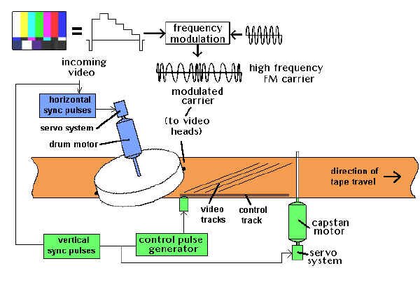
The capstan servo, on the other hand, is trying to ensure that the tape is being pulled through the videotape recorder at a very constant speed. During record, the capstan motor runs at a certain speed, which is compared to the timing of the incoming video's vertical sync pulses. While this is going on, a control track is being laid down on the video tape. This is a pulse for every frame of video - about 30 pulses a second. On playback, the capstan servo looks at the control track and makes sure that the tape is being played back at exactly the right speed. In broadcast VTRs, this is often referenced to the station's external vertical sync pulses.
The control track signal is also a basis for setting up the tape's position relative to the video heads' ability to pick up the tracks recorded on the tape. The speed is adjusted during the "lock up" period just after pressing the play button, so the video tracks line up precisely with the video heads sweeping by. This process is known as "tracking", and it usually takes a couple of seconds to take hold. That's why, when you push play on a VTR, the picture is a little unstable for a couple of seconds - the VTR's servos are getting their act together. And that's why, in a production environment, we roll a VTR a few seconds before we need to take it to air - to allow for the VTR lock-up time.
Television's first decade was the era of live TV. Most original programming was broadcast when it was produced. This was not by choice - no satisfactory recording method except photographic film was available. Many live shows actually were televised twice for different time zones.

It was possible to make a record of a show, a film shot from the screen of a broadcast quality monitor, called a kinescope recording. These recordings were frequently made for use by stations beyond the reach of cable or microwave interconnections with the networks. Because kinescope recordings were expensive and of poor quality, almost from the start of television, engineers searched for a way to record video images on magnetic tape.
In the 1950s, audio tape recordings were widely used on radio, and tape recorders were becoming popular on the consumer market. It was logical that if signals representing audio could be stored on tape, their video counterparts also could be recorded. The problem was that the video signal was far more complex, and the frequencies involved were much higher than in audio.
Analog Videotape Recording Principles
Getting The Signal On Tape
We've got a real problem when we try to record full blown video using a method similar to what we do with audio.
Basic physics states that the highest frequency you can record on magnetic tape is determined by two things. One is how fast the tape travels by the head, and the other is how narrow the head gap is (the space between the two poles on a recording head).
The formula is
Fmax = Vtape / 2 x Wgap.

This means that the maximum frequency you can record is equal to the velocity of the tape as is passes by the head, divided by twice the width of the tape head's gap.
In audio, the highest frequency that has to be recorded is about 20,000 cycles per second. This means that, at 15 inches per second tape speed, you'll need a head gap of .000375 of an inch (20,000 = 15 / 2 x Wgap, or Wgap = 15 / 2 x 20000 = .000375.) This was totally manageable in the 1950s, and made for excellent quality audio recordings. In fact, head gaps could be made as small as .00006 inches (about 1/16000 of an inch wide), meaning audio recordings as slow as 3 3/4 inches per second sounded fine.
But, we digress. Just keep in mind that .00006 of an inch head gap width.
The video signal has frequencies up to 4.2 million Hz in it.Using our now well-worn formula, we plug in the numbers, and come up with a tape speed of 504 inches per second! (4200000 Hz x 2 x .00006 gap width = 504 inches per second.) A half hour recording at this speed would require 75,600 feet of videotape (a little more than 14 miles). This just won't do. But we tried anyway:
November, 1951: The Electronics Division of Bing Crosby Enterprises demonstrated a black and white videotape recorder with twelve fixed recording heads. Using high speed head switching, 1" tape and 100 inches per second tape speed, a 1.7 MHz recording is made on reels that hold 16 minutes of program material - and 8000 feet of tape.
1952: The BBC showed off VERA (Vision Electronic Recording Apparatus), which uses two video tracks, tape speeds of 200 inches per second - and quite low resolution.
December, 1953: RCA displayed their black and white system - one continuous video track, with a 17" reel of 1/4" wide tape, moving at 360 inches per second. Later that month, RCA proved that they could perform the same feat in colour. They used a 17" reel of �" wide tape, three video tracks (R, G, and B) along with a sync pulse track, still running at 360 inches per second, and a recording time of...four minutes.


How The Quad Did It

How The Quad Works (and, why we care...)
Here's a little nitty-gritty on what the guys at Ampex designed into their machine.In one second, the head drum rotates 240 times, placing 960 short tracks on the videotape. The tape is 2" wide, but room is left for audio, control track, and blank, separating "guard bands" between all of the tracks. Therefore, each video track is about 1 4/5 inches long. To allow uninterrupted output from the switched heads, only 1 5/8 inches is used for fresh video - the rest is overlap from the previous track�s video.
If we do the math on the Ampex system, we find out that the effective tape-to-head speed is 1560 inches per second. (960 tracks per second x 1.625 inches = 1560 i.p.s.) Using our familiar formula (1560 / 2 x .00006 = 13,000,000), this means we can record a frequency of up to 13 MHz - lots of room for our 4.2 MHz video signal. It's not quite that simple, however.

The next problem is one of the strength of a signal relative to its frequency. If we try to record a full-response signal directly on tape, we find out that the higher the frequency of a recorded signal, the greater the playback output from the tape. Conversely, the lower the frequency, the lower the playback output.
This causes us grief because we are trying to put on videotape a signal between 30 Hz and 4,200,000 Hz. This is a 140,000:1 ratio. And that, in turn, means that the playback voltage at 30 Hz will be 1/140,000 as strong as that at 4.2 MHz. Expressed as dB (like audio), this ends up being a range from lowest to highest of about 103 dB. That�s like trying to record a quiet conversation and an airport runway at the same time. This is not good. What to do?

Using a super equalizer to hold down the higher frequencies (thereby making the frequencies more "even" to one another) is one idea. Unfortunately, even today (let alone in 1956), most amplifiers and equalizers have electronic noise in them below about 60 dB - that's a long way from our 103 dB required range. With this method, all of our low frequencies would be hopelessly lost in the noise.
The solution lies in a device called a modulator. A modulator is a sort of valve. One signal, called a carrier, is sent into the modulator. A second signal, the modulating one, varies a parameter of the carrier - either (1) its level (or "amplitude") or (2) its (otherwise constant) frequency. The output is either an "amplitude modulation" or a "frequency modulation" of the input signal; known as AM and FM to most radio listeners.

What we're going to use to solve our problem is frequency modulation. A carrier of 8.6 MHz is modulated by the incoming video (which may be up to 4.2 MHz). The modulator output will vary from 4.4 MHz to 12.8 MHz. (8.6 - 4.2 = 4.4 MHz; 8.6 + 4.4 = 12.8 MHz.) Within these fluctuations is a replica of the program video.
What's important to us is the ratio of the highest to lowest frequencies on the tape. That's now about 3:1 (12.8 : 4.4). This is a little less than a 10 dB difference. Any noise in any electronic amplifiers we use will be away back at -60 dB; an excellent safety margin.
Now, to use this modulated system, we'll need to be able to record up to 13 MHz of information on our VTR. With the quad system, and its effective tape to head speed of 1560 inches, we have that recording capacity. What a coincidence...

Getting The Signal Off The Tape
The demodulator (If there was a modulator you just had to know there'd be a demodulator!) has the reverse function of the modulator - it takes the high frequency signal from the tape and retrieves the video signal from it. This fundamental video signal is then put through various processing circuitry to make it stable and to adjust its levels, at which point it is like any other video source.
Of course, it's more complicated than that. We've glossed over all kinds of things like...
Servos and Time Base Correctors
Keeping Track of the Tracks
Drum and Capstan Servos
A servo, in general terms, is an automatic control mechanism in which the output of a device is compared with a stable input reference, so corrections can be made.
Consider the following predicament. You've been chosen to keep the speed of a fan motor constant. To do that, we've supplied you with some equipment - a knob to speed up and slow down the fan, and a little counter that's attached to the fan's motor shaft. Every second, the counter starts counting the revolutions of the fan motor. Your job is to keep the counter always at 100 counts per second - no more, no less.
In the first second, the counter counts up to 102; you turn the speed control down a little bit, to slow down the fan. In the next second, the counter only counts up to 97 (you went too far); you turn up the knob a little bit. In the next second, the counter is up to 99; you turn it up a tiny bit more. The subsequent count says you're up to 101; you back off the knob a little bit. And so on...
You're a servo. You're continually comparing the speed of the fan to a constant (100), and adjusting the speed to try and match it. Now get rid of the knob, the little counter display, and your hand... and do it all electronically. That's an electronic servo

The Drum Servo
The drum servo is trying to keep a constant speed for the video heads as they go across the videotape. During record, it looks at the incoming video's horizontal sync pulses and ensures that the VTR lays down the proper tracks for each frame of video. During playback, the drum servo can either lock to the playback video itself, or an external reference from a central sync generator (within the broadcast facility), and ensures that it plays back the correct video tracks to reproduce the video.


Time Base CorrectionAll VTRs are mechanical devices, and there is a limit to the timing accuracy on playback that can be achieved. The limit is set by the mechanical accuracy of headwheel bearings and motors, and a certain minimum variation in tape quality along the length and width of the tape. Also, gradual and sudden variations of tape guide adjustment and tape path during extended use may cause instability. Time base correctors are used to take out the remaining mechanical jitters in videotape playback so that the signal is stable for broadcast use.

Analog VTR Formats
Up until now, we've been concentrating pretty much on an outdated videotape format - 2" quad. Why? Because the quad was the venerable workhorse of television videotape for the first twenty years, until the mid-1970s. But there's more to it than that.

A 2" VTR embodies all the principles used in modern helical scan machines (which have replaced the quad for the last 25 years), but in ways that are easy for all to see. Indeed, each component and section of a quad can be physically removed and studied further. By contrast, modern VTRs are often highly centralized marvels of construction; often more than one subsystem will be on a single printed circuit board - or even within one integrated circuit chip.

Betacam and M-II (Component Recording)These systems solve the problem of recording the NTSC signal by recording unencoded component signals (called Y, I, Q or Y, R-Y, B-Y), usually on two separate video tracks, one after the other. The process takes advantage of the fact that the chrominance components can share a channel, because of their narrower bandwidth. The tape typically runs six times as fast as consumer machines, though the cassettes used are physically similar. These machines have taken advantage of the newer head and tape technology developed for the consumer video recorders.

They achieve an excellent luminance performance, if not quite as good as analog studio NTSC recorders. Their chrominance performance is superior to most other VTRs, however, since they treat chrominance information as a baseband signal, recorded on its own track. This makes it less susceptible to noise than the high-frequency modulated subcarriers present in NTSC direct colour recording.
Best results with these systems are achieved by remaining in the component format whenever possible. This includes shooting with a camera that has a component output, and editing in component modes. In production editing, this requires a component switcher as well.
In editing situations, the four field colour sequence of the NTSC system is no longer a restriction - you can now edit on every frame of video. Being only able to edit on every fourth field was a result of the requirement to achieve the proper subcarrier phase sequence in edited recordings, but the new component systems have no subcarrier, so there is no longer a worry about colour framing.
This format was developed by Sony and is designed around the elements of the Betamax machine, using the same cassette and drum size. Tape motion and drum rotation are in the same direction. The luminance and chrominance tracks are of the same width, separated by guard bands. The two tracks have azimuth offsets of +15 and -15 degrees, for a total offset of 30 degrees. The format includes two normal audio channels, plus a time code and control code track, and a control track.
The chrominance components recorded are R-Y and B-Y. These are equal bandwidth colour difference signals that are compressed in time by a factor of 2:1. This process doubles the bandwidth occupied by the signals. These compressed signals are recorded such that the chroma track records a line of R-Y and a line of B-Y in the time it takes to record one line of luminance. This process involves time delays, so the luminance and chrominance recorded on a pair of tracks do not, in fact, come from quite the same video line. This timing problem is corrected on playback, so that the re-expanded chrominance is recombined with its proper luminance signal.

The capstan servo, on the other hand, is trying to ensure that the tape is being pulled through the videotape recorder at a very constant speed. During record, the capstan motor runs at a certain speed, which is compared to the timing of the incoming video's vertical sync pulses. While this is going on, a control track is being laid down on the video tape. This is a pulse for every frame of video - about 30 pulses a second. On playback, the capstan servo looks at the control track and makes sure that the tape is being played back at exactly the right speed. In broadcast VTRs, this is often referenced to the station's external vertical sync pulses.
The control track signal is also a basis for setting up the tape's position relative to the video heads' ability to pick up the tracks recorded on the tape. The speed is adjusted during the "lock up" period just after pressing the play button, so the video tracks line up precisely with the video heads sweeping by. This process is known as "tracking", and it usually takes a couple of seconds to take hold. That's why, when you push play on a VTR, the picture is a little unstable for a couple of seconds - the VTR's servos are getting their act together. And that's why, in a production environment, we roll a VTR a few seconds before we need to take it to air - to allow for the VTR lock-up time.
Television's first decade was the era of live TV. Most original programming was broadcast when it was produced. This was not by choice - no satisfactory recording method except photographic film was available. Many live shows actually were televised twice for different time zones.
It was possible to make a record of a show, a film shot from the screen of a broadcast quality monitor, called a kinescope recording. These recordings were frequently made for use by stations beyond the reach of cable or microwave interconnections with the networks. Because kinescope recordings were expensive and of poor quality, almost from the start of television, engineers searched for a way to record video images on magnetic tape.
In the 1950s, audio tape recordings were widely used on radio, and tape recorders were becoming popular on the consumer market. It was logical that if signals representing audio could be stored on tape, their video counterparts also could be recorded. The problem was that the video signal was far more complex, and the frequencies involved were much higher than in audio.
Analog Videotape Recording Principles
Getting The Signal On Tape
We've got a real problem when we try to record full blown video using a method similar to what we do with audio.
Basic physics states that the highest frequency you can record on magnetic tape is determined by two things. One is how fast the tape travels by the head, and the other is how narrow the head gap is (the space between the two poles on a recording head).
The formula is
Fmax = Vtape / 2 x Wgap.
Why there is a limit to how high a frequency you can record
This means that the maximum frequency you can record is equal to the velocity of the tape as is passes by the head, divided by twice the width of the tape head's gap.
In audio, the highest frequency that has to be recorded is about 20,000 cycles per second. This means that, at 15 inches per second tape speed, you'll need a head gap of .000375 of an inch (20,000 = 15 / 2 x Wgap, or Wgap = 15 / 2 x 20000 = .000375.) This was totally manageable in the 1950s, and made for excellent quality audio recordings. In fact, head gaps could be made as small as .00006 inches (about 1/16000 of an inch wide), meaning audio recordings as slow as 3 3/4 inches per second sounded fine.
But, we digress. Just keep in mind that .00006 of an inch head gap width.
The video signal has frequencies up to 4.2 million Hz in it.Using our now well-worn formula, we plug in the numbers, and come up with a tape speed of 504 inches per second! (4200000 Hz x 2 x .00006 gap width = 504 inches per second.) A half hour recording at this speed would require 75,600 feet of videotape (a little more than 14 miles). This just won't do. But we tried anyway:
November, 1951: The Electronics Division of Bing Crosby Enterprises demonstrated a black and white videotape recorder with twelve fixed recording heads. Using high speed head switching, 1" tape and 100 inches per second tape speed, a 1.7 MHz recording is made on reels that hold 16 minutes of program material - and 8000 feet of tape.
1952: The BBC showed off VERA (Vision Electronic Recording Apparatus), which uses two video tracks, tape speeds of 200 inches per second - and quite low resolution.
December, 1953: RCA displayed their black and white system - one continuous video track, with a 17" reel of 1/4" wide tape, moving at 360 inches per second. Later that month, RCA proved that they could perform the same feat in colour. They used a 17" reel of �" wide tape, three video tracks (R, G, and B) along with a sync pulse track, still running at 360 inches per second, and a recording time of...four minutes.
BBC�s VERA, 1952
RCA prototype VTR, 1953
How The Quad Did It
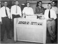
The Ampex guys, 1956
The breakthrough finally came in 1956 from a team of engineers working at Ampex. They solved the problem by mounting the recording heads on a drum that revolved at high speed (14,400 rpm), impressing the signal crosswise on the tape. The actual head-to-tape speed was very high, but the tape transport moved the tape at a relatively slow speed. This was the "quad," so called because of its use of four recording heads. It used tape 2 inches wide
Here's a little nitty-gritty on what the guys at Ampex designed into their machine.In one second, the head drum rotates 240 times, placing 960 short tracks on the videotape. The tape is 2" wide, but room is left for audio, control track, and blank, separating "guard bands" between all of the tracks. Therefore, each video track is about 1 4/5 inches long. To allow uninterrupted output from the switched heads, only 1 5/8 inches is used for fresh video - the rest is overlap from the previous track�s video.
If we do the math on the Ampex system, we find out that the effective tape-to-head speed is 1560 inches per second. (960 tracks per second x 1.625 inches = 1560 i.p.s.) Using our familiar formula (1560 / 2 x .00006 = 13,000,000), this means we can record a frequency of up to 13 MHz - lots of room for our 4.2 MHz video signal. It's not quite that simple, however.
Track layout on a 2" quadruplex videotape machine
The next problem is one of the strength of a signal relative to its frequency. If we try to record a full-response signal directly on tape, we find out that the higher the frequency of a recorded signal, the greater the playback output from the tape. Conversely, the lower the frequency, the lower the playback output.
This causes us grief because we are trying to put on videotape a signal between 30 Hz and 4,200,000 Hz. This is a 140,000:1 ratio. And that, in turn, means that the playback voltage at 30 Hz will be 1/140,000 as strong as that at 4.2 MHz. Expressed as dB (like audio), this ends up being a range from lowest to highest of about 103 dB. That�s like trying to record a quiet conversation and an airport runway at the same time. This is not good. What to do?
Why we don�t record baseband video onto the tape directly
Using a super equalizer to hold down the higher frequencies (thereby making the frequencies more "even" to one another) is one idea. Unfortunately, even today (let alone in 1956), most amplifiers and equalizers have electronic noise in them below about 60 dB - that's a long way from our 103 dB required range. With this method, all of our low frequencies would be hopelessly lost in the noise.
The solution lies in a device called a modulator. A modulator is a sort of valve. One signal, called a carrier, is sent into the modulator. A second signal, the modulating one, varies a parameter of the carrier - either (1) its level (or "amplitude") or (2) its (otherwise constant) frequency. The output is either an "amplitude modulation" or a "frequency modulation" of the input signal; known as AM and FM to most radio listeners.
Types of modulation (A.M. and F.M.)
What's important to us is the ratio of the highest to lowest frequencies on the tape. That's now about 3:1 (12.8 : 4.4). This is a little less than a 10 dB difference. Any noise in any electronic amplifiers we use will be away back at -60 dB; an excellent safety margin.
Now, to use this modulated system, we'll need to be able to record up to 13 MHz of information on our VTR. With the quad system, and its effective tape to head speed of 1560 inches, we have that recording capacity. What a coincidence...
Getting The Signal Off The Tape
The demodulator (If there was a modulator you just had to know there'd be a demodulator!) has the reverse function of the modulator - it takes the high frequency signal from the tape and retrieves the video signal from it. This fundamental video signal is then put through various processing circuitry to make it stable and to adjust its levels, at which point it is like any other video source.
Of course, it's more complicated than that. We've glossed over all kinds of things like...
Servos and Time Base Correctors
Keeping Track of the Tracks
When a videotape is recorded, there must be a way of letting the videotape recorder know later on just when and where the video tracks were laid down, so they may be played back reliably.
In addition, the motor spinning our rotating video heads (the head drum motor) and the motor actually pulling the tape through the transport (the capstan motor) must be kept running at a very constant, identifiable speed, referenced to the incoming video. We do it with a servo.
Drum and Capstan Servos
A servo, in general terms, is an automatic control mechanism in which the output of a device is compared with a stable input reference, so corrections can be made.
Consider the following predicament. You've been chosen to keep the speed of a fan motor constant. To do that, we've supplied you with some equipment - a knob to speed up and slow down the fan, and a little counter that's attached to the fan's motor shaft. Every second, the counter starts counting the revolutions of the fan motor. Your job is to keep the counter always at 100 counts per second - no more, no less.
In the first second, the counter counts up to 102; you turn the speed control down a little bit, to slow down the fan. In the next second, the counter only counts up to 97 (you went too far); you turn up the knob a little bit. In the next second, the counter is up to 99; you turn it up a tiny bit more. The subsequent count says you're up to 101; you back off the knob a little bit. And so on...
You're a servo. You're continually comparing the speed of the fan to a constant (100), and adjusting the speed to try and match it. Now get rid of the knob, the little counter display, and your hand... and do it all electronically. That's an electronic servo

"The human servo"
The Drum Servo
The drum servo is trying to keep a constant speed for the video heads as they go across the videotape. During record, it looks at the incoming video's horizontal sync pulses and ensures that the VTR lays down the proper tracks for each frame of video. During playback, the drum servo can either lock to the playback video itself, or an external reference from a central sync generator (within the broadcast facility), and ensures that it plays back the correct video tracks to reproduce the video.
Time Base CorrectionAll VTRs are mechanical devices, and there is a limit to the timing accuracy on playback that can be achieved. The limit is set by the mechanical accuracy of headwheel bearings and motors, and a certain minimum variation in tape quality along the length and width of the tape. Also, gradual and sudden variations of tape guide adjustment and tape path during extended use may cause instability. Time base correctors are used to take out the remaining mechanical jitters in videotape playback so that the signal is stable for broadcast use.
The first quad VTRs had two devices within them. The AMTEC (Ampex Tape Error Corrector), the first analog timebase corrector, was essentially a series of electronically variable delay lines used to compensate for the playback timebase error. As the head drum speed deviations were detected, a signal representing these errors would be sent to the AMTEC, and the video signal would be delayed as necessary to compensate for the instability. The COLORTEC was later designed for less major errors, to provide a stable colour playback signal.
Today, modern timebase correctors not only allow us to compensate for timebase errors, but, since they're digitizing the video anyway (usually a frame at a time), allow us to adjust video, black and chroma levels, hue. They also frequently offer special effects like strobing and freezing of frames and fields. Finally, this correction technology is used in not only composite video, but component and S-VHS video formats as well.
How TBCs work
Up until now, we've been concentrating pretty much on an outdated videotape format - 2" quad. Why? Because the quad was the venerable workhorse of television videotape for the first twenty years, until the mid-1970s. But there's more to it than that.
Quad head drum
Betacam and M-II (Component Recording)These systems solve the problem of recording the NTSC signal by recording unencoded component signals (called Y, I, Q or Y, R-Y, B-Y), usually on two separate video tracks, one after the other. The process takes advantage of the fact that the chrominance components can share a channel, because of their narrower bandwidth. The tape typically runs six times as fast as consumer machines, though the cassettes used are physically similar. These machines have taken advantage of the newer head and tape technology developed for the consumer video recorders.
They achieve an excellent luminance performance, if not quite as good as analog studio NTSC recorders. Their chrominance performance is superior to most other VTRs, however, since they treat chrominance information as a baseband signal, recorded on its own track. This makes it less susceptible to noise than the high-frequency modulated subcarriers present in NTSC direct colour recording.
Best results with these systems are achieved by remaining in the component format whenever possible. This includes shooting with a camera that has a component output, and editing in component modes. In production editing, this requires a component switcher as well.
In editing situations, the four field colour sequence of the NTSC system is no longer a restriction - you can now edit on every frame of video. Being only able to edit on every fourth field was a result of the requirement to achieve the proper subcarrier phase sequence in edited recordings, but the new component systems have no subcarrier, so there is no longer a worry about colour framing.
This format was developed by Sony and is designed around the elements of the Betamax machine, using the same cassette and drum size. Tape motion and drum rotation are in the same direction. The luminance and chrominance tracks are of the same width, separated by guard bands. The two tracks have azimuth offsets of +15 and -15 degrees, for a total offset of 30 degrees. The format includes two normal audio channels, plus a time code and control code track, and a control track.
The chrominance components recorded are R-Y and B-Y. These are equal bandwidth colour difference signals that are compressed in time by a factor of 2:1. This process doubles the bandwidth occupied by the signals. These compressed signals are recorded such that the chroma track records a line of R-Y and a line of B-Y in the time it takes to record one line of luminance. This process involves time delays, so the luminance and chrominance recorded on a pair of tracks do not, in fact, come from quite the same video line. This timing problem is corrected on playback, so that the re-expanded chrominance is recombined with its proper luminance signal.
Betacam tracks (note separate luminance [Y] and chroma [C] tracks)
Since the R-Y and B-Y signals never share the same track at once, there is no chance of crosstalk between them. This process of alternating the two components is called "Component Time Division Multiplexing" (CTDM).
The M-II format is very similar to the Betacam format.
http://www.danalee.ca/ttt/video_recording.htm
Subscribe to:
Posts (Atom)
Popular Posts
-
 Lihat Gambar Jika Resistor yang memiliki 4 gelang warna : gelang 1 dan 2 dibaca sesuai kode warna gelang 3 adalah faktor pengali gelang 4 ad...
 -
Andromax-C JellyBean ROOTING 1. Andromax-C JellyBean 2. Framaroot Link : http://forum.xda-developers.com/show….php?t=2130276 Mirror Link G...
ABOUT ME
N a m e
Ulfar
H o m e t o w n
Indonesia

Ulfar
H o m e t o w n
Indonesia